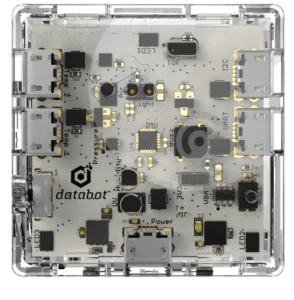
Databot is far more than a sensor device. It is a compact scientific laboratory that allows children and teachers to explore light, sound, temperature, motion, magnetism and many other environmental parameters in real time.
However, when we add motion, everything changes.
By connecting a servo motor through the PCA9685 PWM driver board, Databot moves from being a device that only measures the world to one that can physically respond to it. A change in light can rotate a mechanism. A sound threshold can trigger a moving structure. A temperature shift can open or close a system automatically. Suddenly, data becomes action.
In this blog, we will go step by step through the full connection process, explain the wiring logic, describe the role of each component and show how this simple extension dramatically expands the creative and engineering possibilities of Databot.
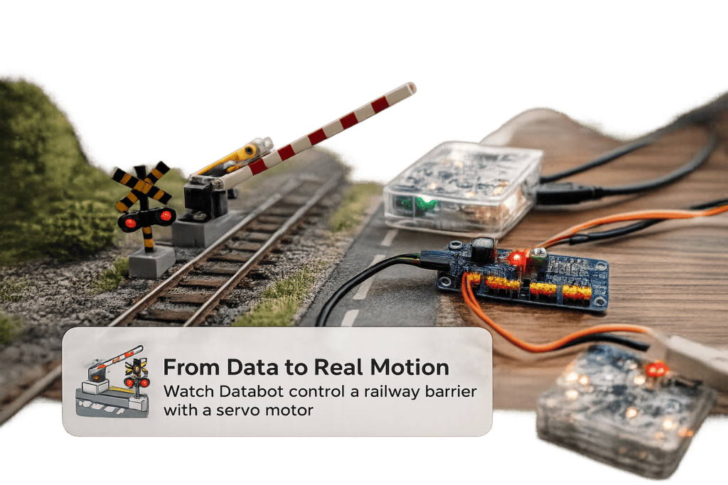
From Data to Real Motion
Imagine a railway crossing barrier that lifts and lowers automatically. A system that reacts to sensor input, environmental conditions, or programmed logic. In this project, Databot controls a miniature railway barrier using a servo motor connected through the PCA9685 driver board. The movement is smooth, precise, and fully programmable.
This is more than a simple mechanical demo. It is a clear demonstration of how data can control infrastructure. A light sensor can trigger the barrier. A sound sensor can detect a signal. A timer can simulate train arrival. With just one servo motor, the project becomes a working model of a smart transport system.
Hardware and Connection Preparation
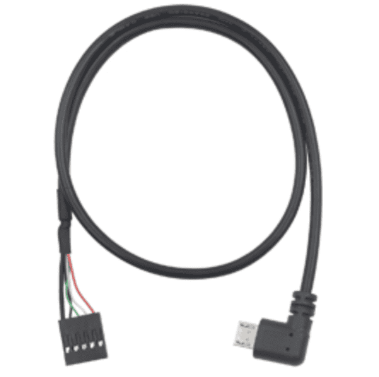
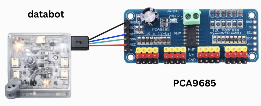
For this setup we need three main components. The Databot device, the PCA9685 PWM driver board, and a standard servo motor. In addition, a custom connection cable is required. This cable allows data exchange between Databot and the PCA9685 through the I2C communication interface.
Programming and testing are performed on a computer using Arduino IDE. This environment allows us to send commands to Databot, control servo angles, and later build behaviour where sensor data directly affects physical movement.
Databot
Micro USB to Dupont
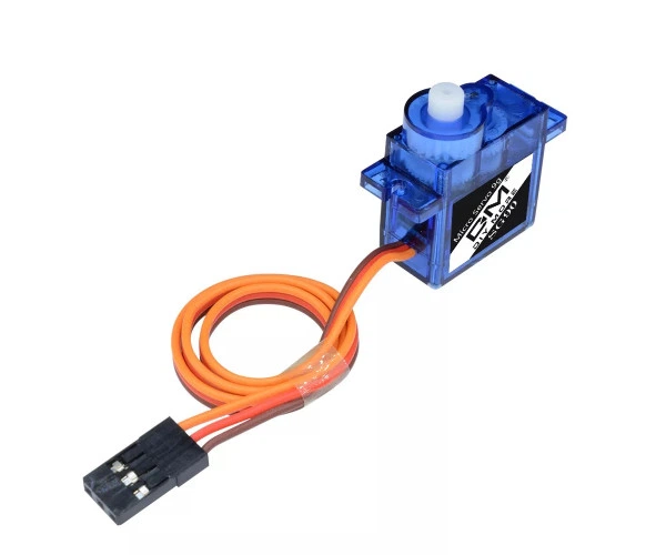
Servo motor
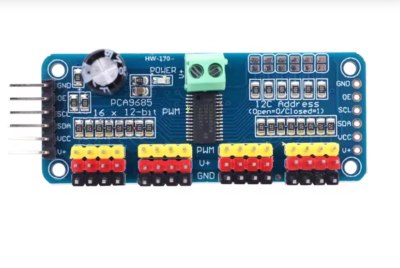
PCA9685
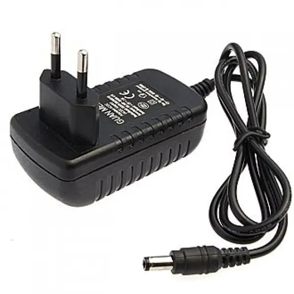
5 volt power supply
Connecting and Testing the PCA9685
Now we move to the first real technical verification step. Before controlling the servo motor, we must confirm that the PCA9685 board correctly communicates with Databot.
Connection logic:
The PCA9685 is connected to Databot using the micro USB to Dupont cable. Communication between the devices is performed over the I2C protocol. The factory default I2C address of the PCA9685 is 0x40.
Testing procedure
Connect Databot to the computer via USB.
Open Arduino IDE.
Select the correct board and port.
Upload an I2C scanner sketch to Databot.
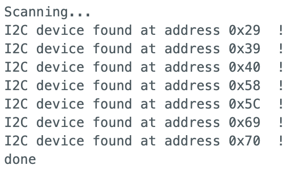
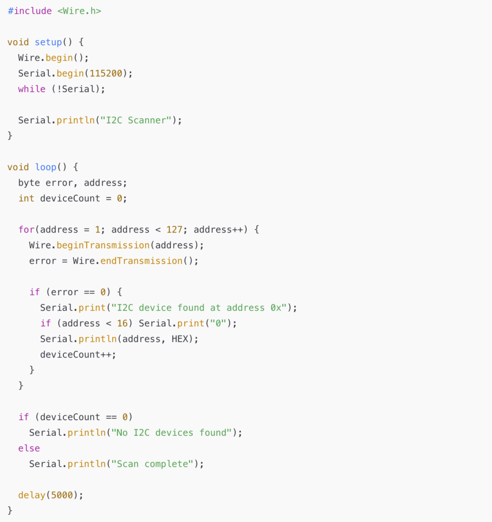
The I2C scanner checks all possible addresses on the bus and reports any detected devices. If everything is connected properly, the Serial Monitor should display the device at address 0x40.
Example I2C scanner code
Open the Serial Monitor at 115200 baud.
If you see:
I2C device found at address 0x40
this confirms that the PCA9685 is properly connected and ready for servo control.
Connecting the Servo Motor and Supplying External Power
Once communication with the PCA9685 has been verified, we can safely move to the next stage: connecting the servo motor and providing dedicated power to the driver board.
Why external power is important
Servo motors require significantly more current than the I2C communication line can provide. If powered incorrectly, the system may behave unpredictably, reset, or even damage components.
For stable operation, the PCA9685 board must receive external power through its screw terminal block. This power source supplies the servo motor directly, while Databot continues to handle communication and control logic.
Servo wiring
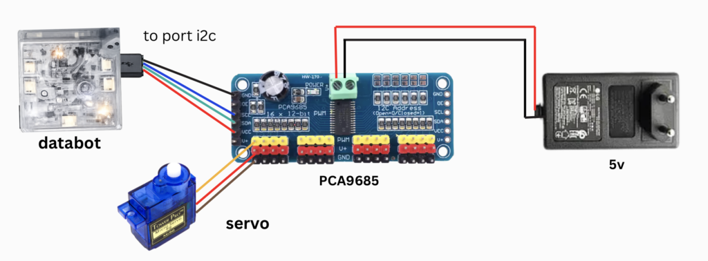
The servo motor connects to one of the PCA9685 output channels using its three wires:
Orange wire – PWM signal – connect to the yellow pin row of the selected channel Red wire – V+ power – connect to the red pin row Brown wire – Ground – connect to the black pin row
Power connection
Two wires from the DC power supply are connected to the green terminal block on the PCA9685:
Positive wire to V+ Negative wire to GND
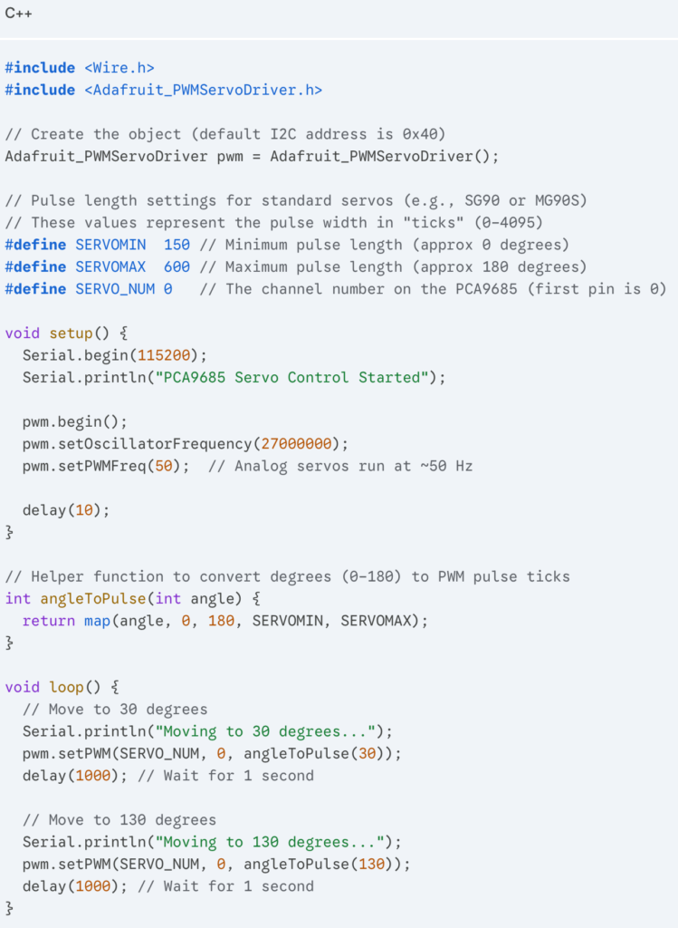
To control the PCA9685 driver with an ESP32 in the Arduino IDE, the most reliable method is using the Adafruit PWM Servo Driver library.
If you haven’t installed the library yet:
Open Arduino IDE.
Go to Sketch -> Include Library -> Manage Libraries…
Search for “Adafruit PWM Servo Driver” and click Install.
After uploading the code, you will see the servo motor begin to move. In that moment, Databot shifts from measuring the world to interacting with it.
One PCA9685 board allows you to control up to 16 servo motors. This means multiple moving parts, coordinated mechanisms, and the foundation for real robotic systems.
The true power of this setup lies in the combination of Databot sensors and servo control. Light, sound, temperature, motion, or magnetic data can instantly trigger mechanical action. Data becomes movement.
This combination transforms simple experiments into intelligent machines and opens the door to building responsive robots and automated systems.