databot is a marvelous device filled with an abundance of different sensors and technology that can sense and measure the world around us as well as communicate with and control other devices. They are so useful everywhere and at all times, opening up endless possibilities of applications. After all, a databot can be useful in a variety of applications, from education to a mountaineering trek in the mountains.
Nevertheless, the human thirst for new discoveries always pushes us to explore and improve. And we provide people with this opportunity.
Today we want to share with you how, using the I2C protocol, you can extend the functionality of a databot by connecting additional sensors and devices to it. Let’s walk together this fascinating path, describing each step of connection.
Let’s dive into the world of research.
What is I2C?
Inter-Integrated Circuit (I2C) is a popular communication protocol used in microcontroller-based systems. It is a two-wire serial communication bus that allows multiple devices to communicate with each other using a single pair of wires. I2C was originally developed by Philips Semiconductors (now NXP Semiconductors) in the early 1980s and has since become a widely adopted standard in the embedded systems industry.
How Does It work?
The basic principle of operation includes two main lines: SDA (Serial Data Line) for information transfer and SCL (Serial Clock Line) for synchronization of the transfer. The exchange starts with the master, which generates a START condition and sends the address of the device with which it wants to communicate. The data is then transmitted sequentially in 8-bit blocks, with each bit accompanied by an SCL pulse. The receiver can send an acknowledgement (ACK) or rejection (NACK) after each byte of data. The exchange is terminated by a STOP condition generated by the master. I2C allows multiple devices to be connected to a single bus, providing convenience and efficiency in numerous electronic applications.
Getting Started
Necessity is the mother of invention, and this is a perfect example of a circumstance that generated a new databot projct and solution. I’ve had the occasional problem where I had a databot with me and I wanted to check CO2 readings – but I did not have a phone or smart device with me to connect to it. Maybe you are facing a similar situation where you would like to see the data output from databot without a smart device. This project solves the challenge beautifully by connecting a dedicated OLED LCD display to databot!
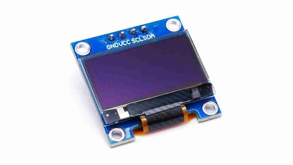
Today we will connect an OLED LCD 0.96 Display to databot using the I2C protocol.
We will learn how to control it and output data.
We will learn how to display sensor readings on the display in real time.
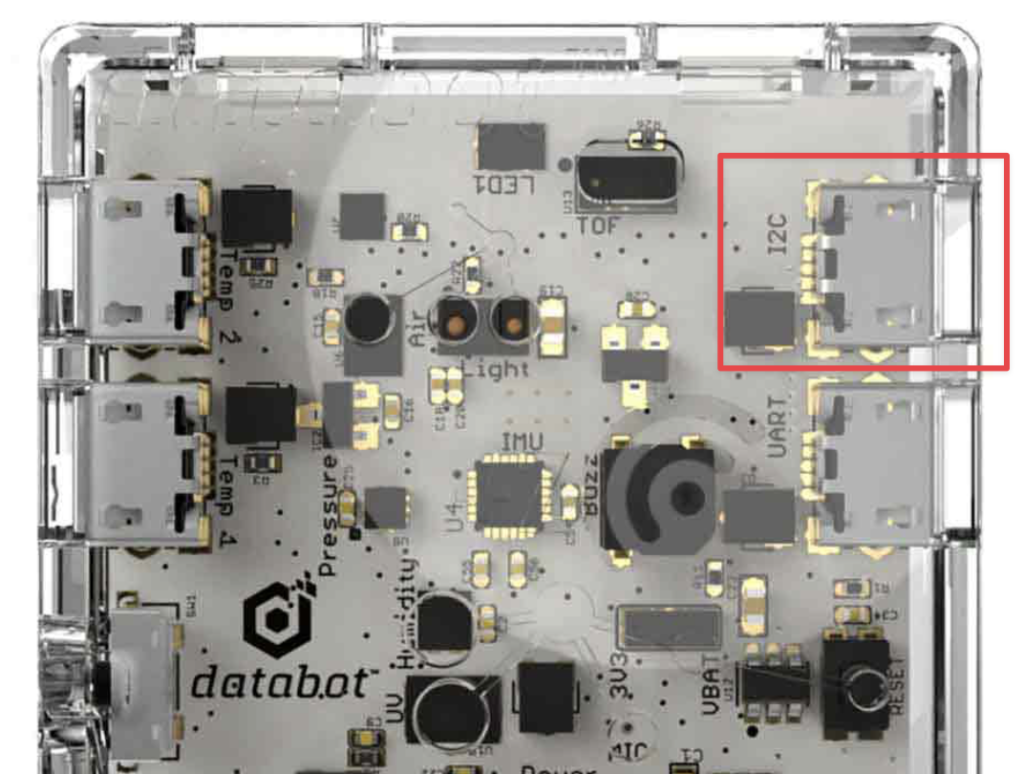
There is an I2C port present on the databot board that enables you to connect to any device that also supports I2C. There are many different sensors and devices using I2C, once you know how to do this the OLED Display, you may have some creative urges to connect more devices!
Let’s look at the connection. For this project it is necessary to create your own cable. Ultimately we will try to have cables available for sale if you don’t like to hack and create your own.
You will need a Micro USB cable. They come in 2 types, a power/charging version with 2 wires and a charge + data version that has 4 wires. You will need a 4-wire cable. These wires will be used to transmit power and data.
Once you have acquired your cable, Cut off the USB 2.0 connector (it is flat and wide). You will be leaving the MicroUSB end attached that matches the databot port.
Strip off part of the plastic sheath as shown parts and see what color the wires are. Wires from different manufacturers can be of different colors. In our case white is 5v, gray GND, yellow SCL, blue SDA. You can look up the specification of your wire on the Internet, try searching for the manufacturer.
If you can’t find the information you will need to identify the wires by using a multi-meter, which is beyond this article.
Connect the wires to your device as shown, in this case the device is the OLED Display.
You have now engineered a custom cable for connecting this display to databot! In this same fashion, you can connect any device to databot.
Connecting databot to Arduino IDE
If you haven’t worked with databot and the Arduino IDE before, we have detailed instructions on how to do it.
We have prepared for you a ready-made code that displays CO2 level information directly on the display in real time. To download the code you need to install 2 additional libraries.
Installing SSD1306 OLED Library
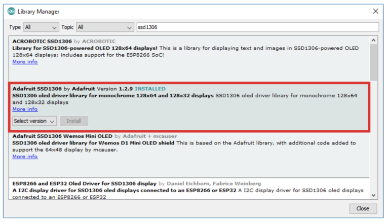
1. Open your Arduino IDE and go to Sketch > Include Library > Manage Libraries. The Library Manager should open.
2. Type “SSD1306” in the search box and install the SSD1306 library from Adafruit.
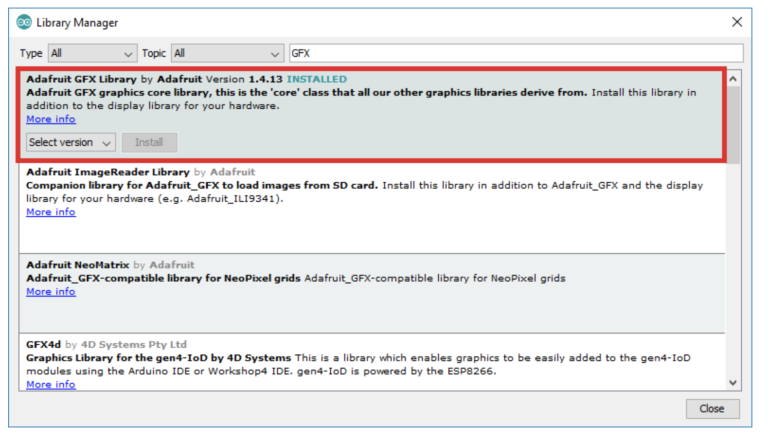
3. After installing the SSD1306 library from Adafruit, type “GFX” in the search box and install the library.
4 – Now all that’s left is to download the code and upload it to databot! Check it out and enjoy. Watch the following video to see it in action, and now that you have the power to drive an external display, what will you do with it?!