In this project, we explore how two powerful educational tools — databot and the BBC micro:bit — can be connected to expand STEM learning opportunities. Thanks to the flexible communication setup, either device can act as the master controller. That means databot can control micro:bit, or micro:bit can control databot, depending on the experiment.
In this tutorial, micro:bit acts as the master, and databot acts as the sensor module, significantly expanding the micro:bit’s capabilities with access to sensors for gas, sound, pressure, temperature, illumination, and more.
This integration enables real-time data collection, scientific exploration, and interactive projects, making it perfect for classrooms, homes, and makerspaces.
What You Need
To set up I2C communication between databot and micro:bit, you’ll need a few essential components. These ensure that both devices can be physically connected and communicate reliably.
databot: Acts as the sensor platform providing environmental and physical measurements.
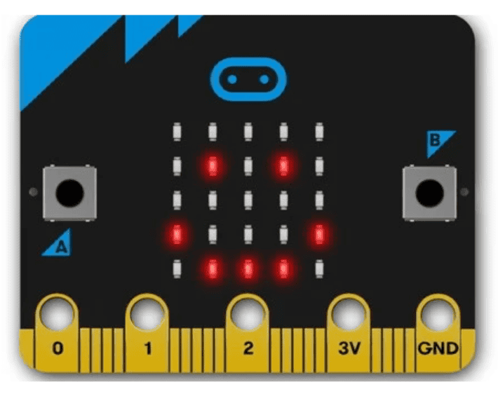
BBC micro:bit: The main controller that reads sensor data and triggers actions.
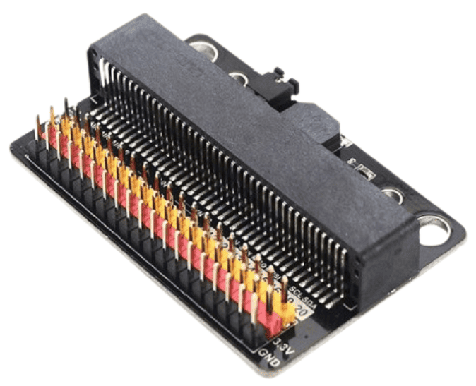
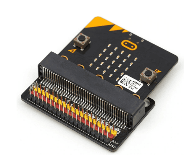
Pin Expansion Board for micro:bit: Provides access to I2C pins (SCL / SDA), 3.3V, and GND for safe wiring.
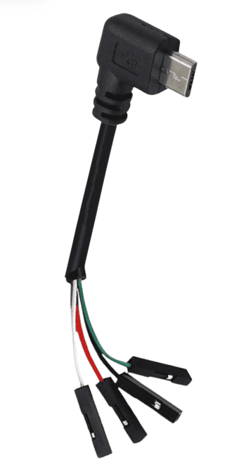
Micro USB to Dupont Cable Adapter: Connects databot to the expansion board via I2C pins.
Wiring & I2C Connection Setup
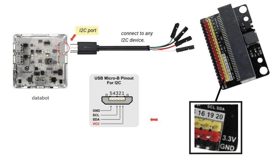
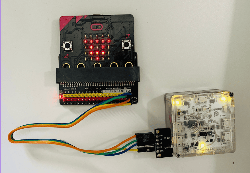
To establish I2C communication between databot and the micro:bit, you will connect four wires: power, ground, and the two I2C data lines.
First, connect the red wire from the databot’s cable to the 3.3V pin on the micro:bit expansion board. This provides power directly from databot to micro:bit. Next, connect the black wire to the GND (ground) pin — this ensures both devices share a common ground, which is required for stable communication.
The remaining two wires are used for data exchange through the I2C interface. Connect one of them to Pin 19, which is the SCL (clock) line, and the other to Pin 20, the SDA (data) line on the expansion board. If your cable wires are not labeled, simply test or check your documentation — only SCL and SDA need to be correctly matched for the communication to work.
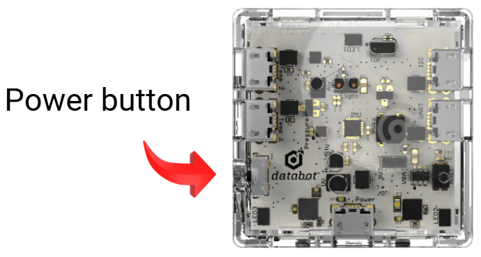
Once these connections are in place, both power and sensor data will travel through the same cable. When you turn on databot, the micro:bit powers up automatically and is ready to communicate — no extra battery packs or power supplies needed.
Why This Setup is Great
Because micro:bit is powered directly from databot, the whole system becomes:
Compact
Wireless battery-free
Ready-to-run
No extra power supplies needed. Once databot turns on — micro:bit powers up and starts communicating immediately. This makes the setup classroom-friendly and easy to repeat.
Connecting and Testing Communication
Step 1: Program micro:bit
In this project, micro:bit acts as the main controller, and databot functions as the sensor device. All logic is programmed directly on the micro:bit.
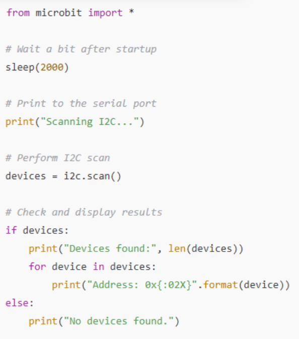
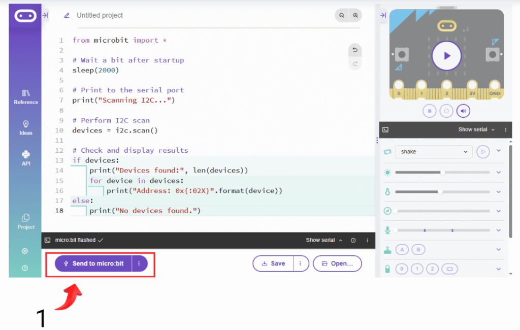
First, connect micro:bit to your computer and open the online Python editor. Then, write a simple I2C scan program to detect connected devices.
This code will scan all devices that are connected via I2C bus
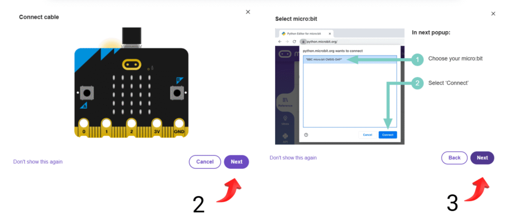
Now it’s time to upload the code to your micro:bit. Just click the “Send to micro:bit” button, then follow the on-screen instructions to connect your micro:bit to the website and transfer the code.
After a successful connection, press the “Send to micro:bit” button again to upload the code to micro:bit
Step 2: Check Detected Devices
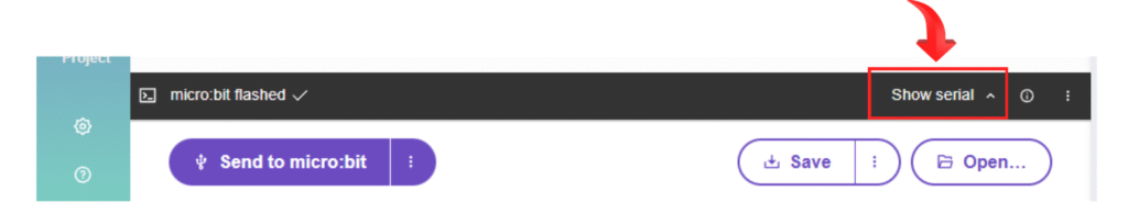
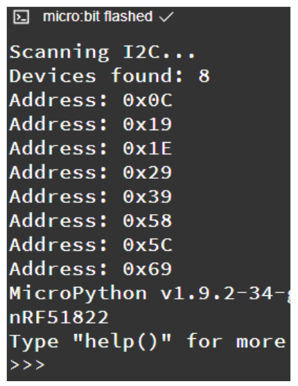
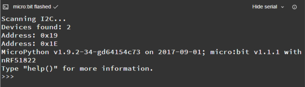
Open the serial port and review the detected I2C addresses.
If you see a similar answer, it means that micro:bit can detect databot.
But if only two addresses appear, it means that micro:bit is only detecting its internal sensors – magnetometer and accelerometer
To ensure that micro:bit can see databot, make sure:
3. If there are still only 2 addresses, try swapping the pins Pin 19 (SCL) and Pin 20 (SDA). Maybe you made the wrong connection. Then scan again.
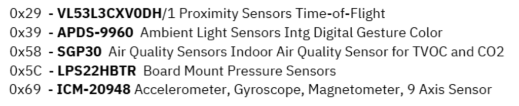
Each sensor is assigned to a specific I2C address. Below is a list of addresses and their associated sensors.
Reading Data from databot Sensors
Once the micro:bit detects databot, you can begin reading sensor values.
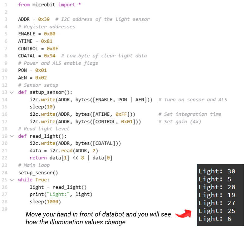
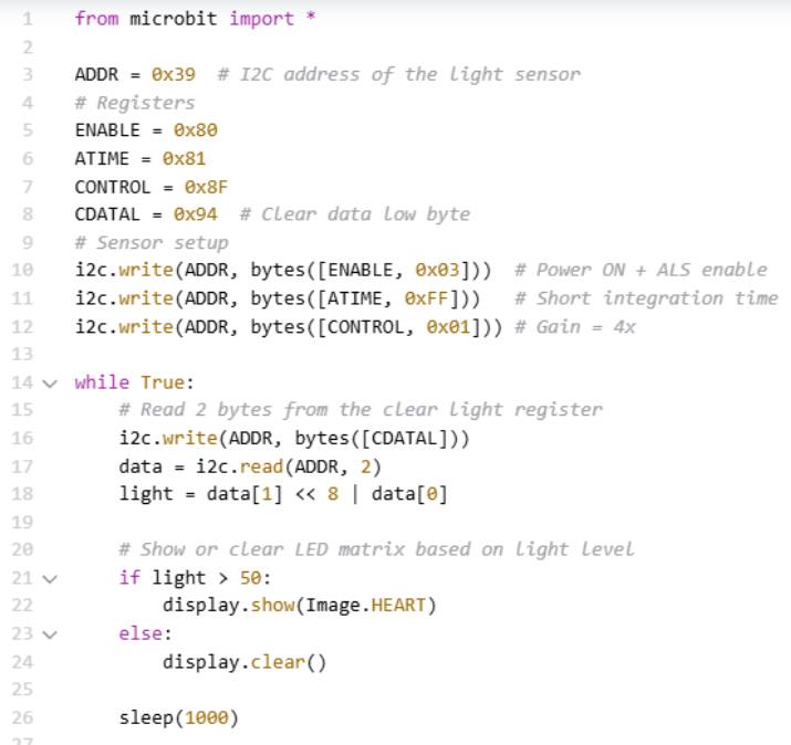
Example: Light Sensor
Write code to display changes in illumination: when you move your hand over databot, illuminance values will change in real-time.
You can also write code for micro:bit to interact with databot. For example, micro:bit will display a heart icon on its LED matrix if the light is more than 50 lm.
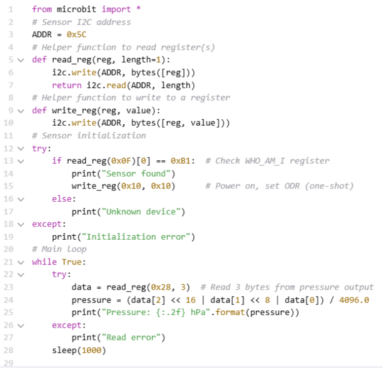
The code below allows you to receive air pressure data from databot:
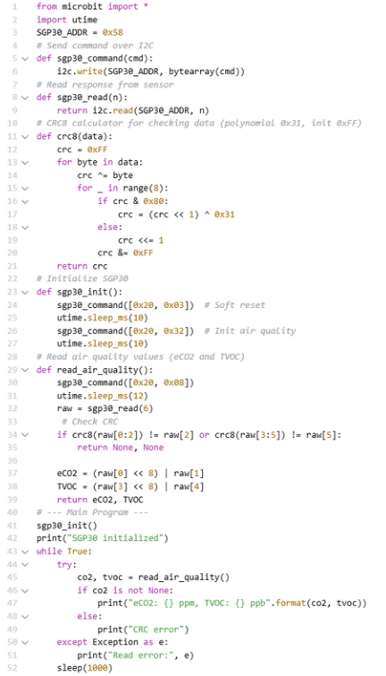
And here is an example of code that allows you to receive TVOC and CO2 data:
Wrapping It All Up
Congratulations! You’ve successfully integrated databot with micro:bit using I2C communication.
With just a few lines of code, you’ve unlocked the ability to read live environmental sensor data — and this is only the beginning. Now you can build smart weather stations, air quality monitors, gesture-controlled robots, classroom scientific experiments, sensor-driven games, and interactions.